Hydraulic flange connections are widely used in high-pressure hydraulic systems where reliable sealing, strength, and easy maintenance are essential. Among common hydraulic flange standards, SAE J518 Code 61 is one of the most widely adopted solutions for industrial and mobile hydraulic applications.
Designed for 3000 PSI class hydraulic systems, SAE J518 Code 61 flanges provide a secure connection method for hydraulic hoses, pumps, valves, and other components. Compared with traditional threaded connections, flange connections offer better resistance to vibration, easier installation, and improved sealing performance in demanding environments.
Understanding SAE J518 Code 61 flange dimensions, pressure ratings, configurations, and selection requirements helps engineers and buyers choose suitable hydraulic connection solutions for their equipment.
SAE J518 Code 61 is a hydraulic flange standard developed by the Society of Automotive Engineers (SAE) for connecting hydraulic components in high-pressure systems. It defines flange dimensions, mounting requirements, pressure capabilities, and connection specifications for hydraulic applications.
A typical SAE J518 flange assembly consists of a flange head, O-ring seal, bolts, and hydraulic ports. The flange creates a strong mechanical connection while the O-ring provides reliable sealing against hydraulic fluid leakage.
Unlike threaded fittings, flange connections distribute pressure loads more evenly across the connection surface. This makes them suitable for applications involving high vibration, shock loads, and frequent pressure changes.
The code 61 flange design is commonly used in hydraulic systems requiring a 3000 PSI pressure class. It is widely applied in construction equipment, industrial machinery, agricultural machinery, and mobile hydraulic systems.
Pressure capability is one of the most important factors when selecting hydraulic flange connections. SAE J518 Code 61 is generally designed for medium to high-pressure hydraulic applications with a working pressure rating of approximately 3000 PSI, depending on flange size and system conditions.
The pressure performance of a sae flange code 61 connection depends on several factors, including flange size, material strength, bolt quality, sealing condition, and installation accuracy.
Compared with higher-pressure flange designs, Code 61 provides a balance between performance and cost. It offers sufficient strength for many industrial hydraulic systems while maintaining a compact and practical design.
When selecting a hydraulic flange connection, engineers should always consider the maximum system pressure rather than only the standard pressure rating. Pressure spikes, temperature changes, and operating environment may affect actual performance.
Accurate dimensions are essential for ensuring compatibility between hydraulic components. The SAE J518 Code 61 flange standard defines key dimensional requirements, including flange head size, bolt spacing, port diameter, and sealing surface design.
Different flange sizes are available to meet various flow requirements and hydraulic system designs. Larger flange sizes generally support higher flow rates and larger hydraulic connections.
| Flange Size | Typical Application | Pressure Class |
|---|---|---|
| 1/2 inch | Compact hydraulic systems | 3000 PSI class |
| 3/4 inch | Industrial machinery and mobile equipment | 3000 PSI class |
| 1 inch and above | Heavy-duty hydraulic applications | 3000 PSI class |
The correct sae 3000 flange dimensions must match the hydraulic equipment port and hose assembly specifications. Incorrect dimensions may result in poor sealing, installation difficulties, or premature component failure.
For equipment manufacturers, maintaining accurate flange dimensions is essential for ensuring reliable hydraulic system performance.
Hydraulic flange connections are available in different configurations to meet various installation requirements. The choice of configuration depends mainly on hose routing, available space, and system layout.
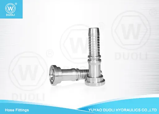
Straight configurations are commonly used where direct connection between hydraulic components is possible. They provide simple installation and minimize flow restrictions.
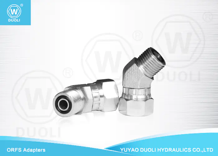
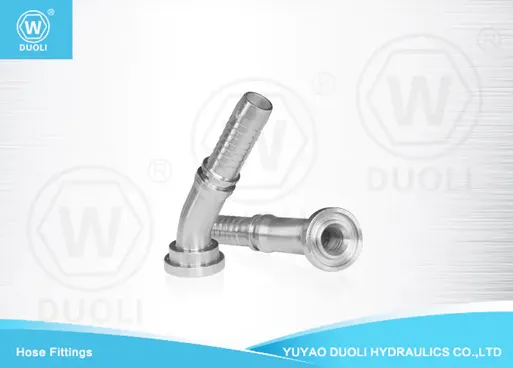
Angled configurations, including 30°, 45°, and 90° designs, are used when hydraulic lines require directional changes. These designs help reduce excessive hose bending and improve installation flexibility.
When selecting a configuration, engineers should consider:
Installation space: Angled flanges are useful in compact hydraulic systems where straight installation is difficult.
Hose routing: Proper orientation helps prevent excessive bending and mechanical stress.
Maintenance requirements: Correct configuration can make inspection and replacement easier.
Using the correct configuration improves hose service life and reduces stress on hydraulic connections.
SAE J518 Code 61 flange connections are widely used in industries where hydraulic reliability and durability are required.
Construction machinery is one of the most common applications. Equipment such as excavators, loaders, cranes, and earthmoving machines often experience vibration and pressure fluctuations, making flange connections a preferred solution.
Industrial hydraulic systems also use sae j518 code 61 flange products for pumps, valves, cylinders, and other hydraulic components. The strong connection design helps maintain stable operation under demanding working conditions.
Agricultural machinery, material handling equipment, and mobile hydraulic systems also benefit from the durability and easy maintenance of Code 61 flange connections.
Because flange connections provide excellent sealing performance and resistance to mechanical stress, they remain an important choice for modern hydraulic equipment.
Proper installation is essential for achieving the expected performance of a SAE J518 Code 61 flange connection. Even high-quality components may fail if installation procedures are incorrect.
When selecting and installing Code 61 flange assemblies, consider the following factors:
Pressure requirements: Confirm that the flange rating matches the maximum working pressure of the hydraulic system.
Dimension compatibility: Verify that the flange size matches the equipment port and hydraulic hose specifications.
Seal condition: Inspect O-rings carefully and replace damaged seals before installation.
Bolt tightening: Follow proper tightening procedures to ensure even pressure distribution.
Operating environment: Consider temperature, vibration, corrosion, and mechanical loads.
Choosing a reliable supplier is also important for ensuring consistent product quality. Duoli Hydraulics provides professional hydraulic connection solutions, including hydraulic flange products designed for demanding industrial applications.
SAE J518 Code 61 is a hydraulic flange standard used for connecting hydraulic components in medium to high-pressure systems. It defines flange dimensions, sealing methods, and performance requirements.
Code 61 flange connections are commonly used in 3000 PSI hydraulic systems, although actual pressure capability depends on flange size, materials, and operating conditions.
The main difference is pressure capability. Code 61 is typically designed for 3000 PSI applications, while Code 62 is designed for higher pressure systems.
They are commonly used in construction machinery, industrial hydraulic equipment, agricultural machinery, and mobile hydraulic systems.
Selection should consider pressure requirements, flange size, hydraulic port compatibility, installation space, and operating environment.
Flange connections provide strong mechanical strength, reliable sealing, and better resistance to vibration compared with many traditional threaded connections.


 English